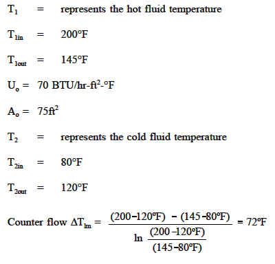
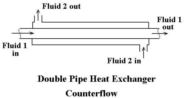
Counter Flow Heat Exchanger Equations
Comparison Of Heat Exchanger Types Parallel Heat Exchanger Cross Flow Heat Exchanger Counter Flow Heat Exchanger Engineers Edge
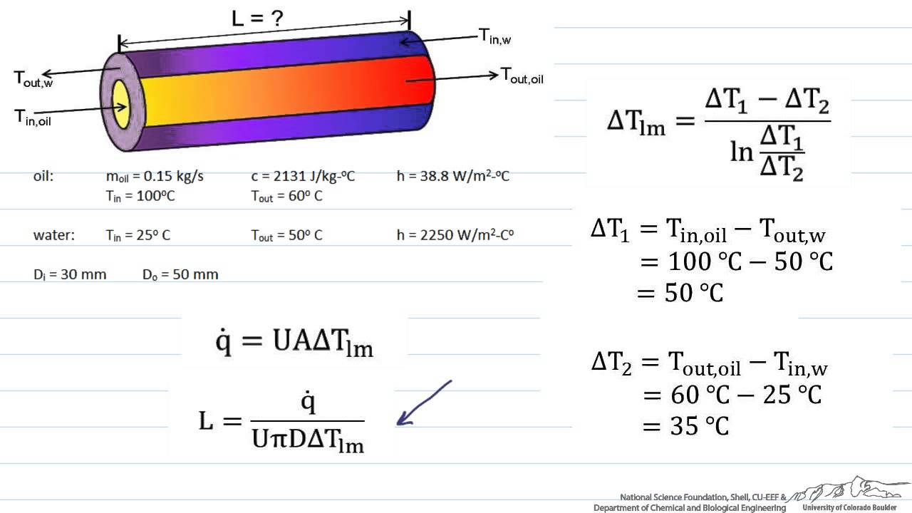
Sizing A Heat Exchanger Parallel Flow Youtube
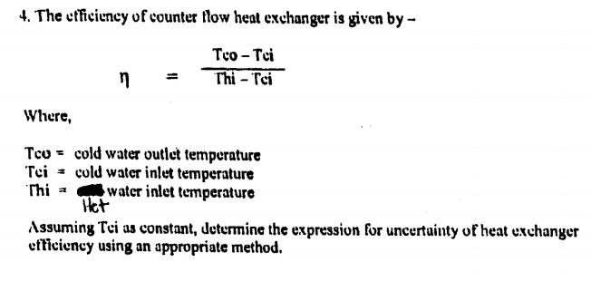
Solved The Efficiency Of Counter Flow Heat Exchanger Is G Chegg Com
18 5 Heat Exchangers
Parallel And Counter Flow Designs Heat Exchangers Engineers Edge Www Engineersedge Com
Why Is A Counter Flow Heat Exchanger Better Than A Parallel Flow Heat Exchanger Quora
For a parallel flow heat exchanger n 0 and for a counterflow heat exchanger n 1.
Counter flow heat exchanger equations.
Heat Exchanger Flow Cross Flow Parallel Flow Counter Flow Heat Exchangers Bright Hub Engineering

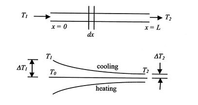
A Counter Flow Heat Exchanger With The Temperature Profile Download Scientific Diagram

Heat Transfer L32 P2 Temperatures For Parallel And Counterflow Heat Exchangers Youtube

Counter Flow Heat Exchanger Outlet Temperature Bio Youtube
Source : pinterest.com
