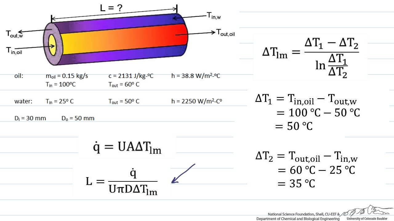
Counter parallel flow heat exchanger tube length calculation.
Counter flow heat exchanger calculator.
A box will be highlighted yellowif it needs input.
Heat exchanger calculations with the heat exchanger design equation require a value for the heat transfer rate q which can be calculated from the known flow rate of one of the fluids its heat capacity and the required temperature change.
Heat transfer q u a tm.
Https engineers academy product level 4 higher national certificate hnc in mechanical engineering in this video tutorial you will learn how to calculate.
Input data in yellow update and reset funtions at bottom of page.
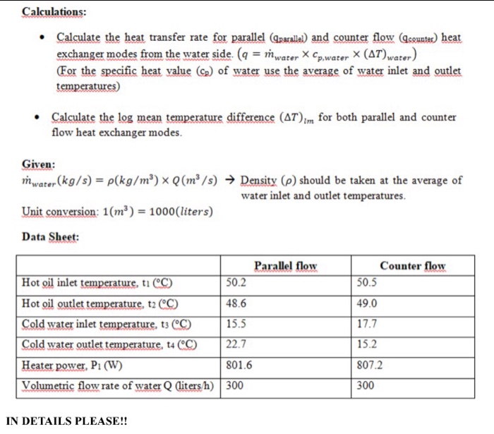
Q m h c ph t hin t hout m c c pc t cout t cin where.
Calculate calculate outlet temperature for hot and cold stream for given flowrates inlet temperature specific heat area of the exchanger and overall heat transfer coefficient u.
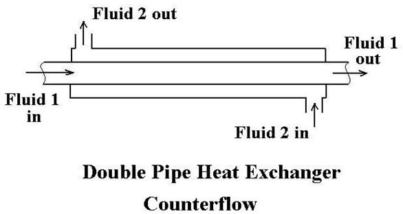
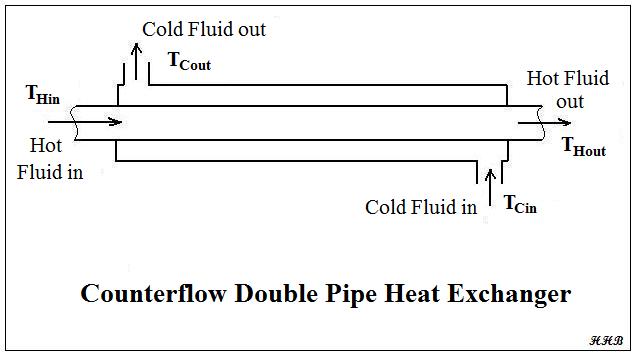
A counter flow heat exchanger is one in which the direction of the flow of oneof the working fluids is opposite to the direction to the flow of the other fluid.
Counter parallel flow heat exchanger tube length calculation.
The simplest heat exchanger is one for which the hot and cold fluids move in the same or opposite directions in a concentric tube or double pipe construction.
Plane wall heat transfer coefficient u 1 1 ho l k 1 h1.
Following is the equation to be used.
Enter the fluid data and enter 5 of the 6 available inputs under flow rates and temperatures.
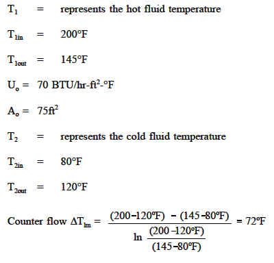
In heat exchanger analysis if the fluid inlet and outlet temperatures are specified or can be determined by simple energy balance the lmtd method can.
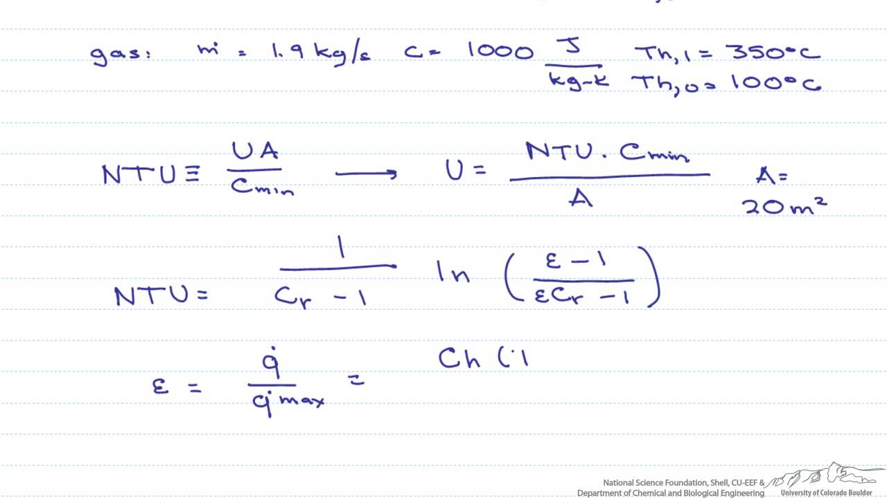
The number of transfer units ntu method is used to calculate the rate of heat transfer in heat exchangers especially counter current exchangers when there is insufficient information to calculate the log mean temperature difference lmtd.
In a parallel flowexchanger both fluids in the heat exchanger flow in the same direction.
In the parallel flow arrangement of figure 18 8 a the hot and cold fluids enter at the same end flow in the same direction and leave at the same end.
Figure 9 represents the directions of fluid flow in the parallel and counter flow exchangers.